Motorcycle Display and Logger
 I recently added a graphic LCD screen to my Goldwing. The new screen
displays battery voltage, battery current (either charging or
discharging), outside temperature, and altitude derived from a pressure
sensor. It is also interfaced to an OEM GPS board and displays exact
time and date, latitude, longitude, current speed, a resettable
odometer, current direction, and altitude derived from the GPS.
I recently added a graphic LCD screen to my Goldwing. The new screen
displays battery voltage, battery current (either charging or
discharging), outside temperature, and altitude derived from a pressure
sensor. It is also interfaced to an OEM GPS board and displays exact
time and date, latitude, longitude, current speed, a resettable
odometer, current direction, and altitude derived from the GPS.
Like most projects, it started out small and simple and grew
from there. I wanted a simple display of battery voltage and
temperature probably on an LED or text based LCD display. Then I talked
to my son and he said I should add battery current as well to provide
the
best idea of the condition of the battery and the charging system and,
while I was at it, why not add altitude since we spend a lot of time
riding in mountains. OK that doesn’t sound too bad. If you’re
interested in all of the technical details, skip ahead to here,
otherwise follow along for the outcome.
 My
first attempt was a 5 digit LED display that I mounted in the blank
panel where a CB would be mounted since I don’t have one on this bike.
The voltage worked great, the temperature worked great, the current
sensor that I wanted to use was not available yet so I didn’t have
current sensing yet, and the altitude worked relatively well but could
be off by +/- 200 feet or so since it was based on an absolute
pressure
sensor and could change with atmospheric pressure. As I said,
it worked
great on the bench, it worked great in the garage, but when I went out
for a ride on a sunny day, which we occasionally have around here, I
couldn’t read the LED at all. If it clouded over or the sun was in
front of me I could read it fine, but I knew that this wouldn’t make
it.
My
first attempt was a 5 digit LED display that I mounted in the blank
panel where a CB would be mounted since I don’t have one on this bike.
The voltage worked great, the temperature worked great, the current
sensor that I wanted to use was not available yet so I didn’t have
current sensing yet, and the altitude worked relatively well but could
be off by +/- 200 feet or so since it was based on an absolute
pressure
sensor and could change with atmospheric pressure. As I said,
it worked
great on the bench, it worked great in the garage, but when I went out
for a ride on a sunny day, which we occasionally have around here, I
couldn’t read the LED at all. If it clouded over or the sun was in
front of me I could read it fine, but I knew that this wouldn’t make
it.
I started looking around for a different display and
eventually ended up with a graphic
LCD from Crystalfontz.
It has a
display area of about 1” X 2-1/8”, LED backlighting, and has
dark
characters on a light background so it is similar to the existing
Goldwing display. Now I needed a way to mount the display and found the
answer at Firecreek
Accessories with a product called a Wing Panel.
They sell it for mounting round gauges but it worked perfectly for my
application. I also have a tank
bag from them and have been very
pleased with it. About the same time I found the display, I also found
a great deal on a CMC Superstar OEM
GPS board on Ebay, so I decided to
interface the GPS board as well.
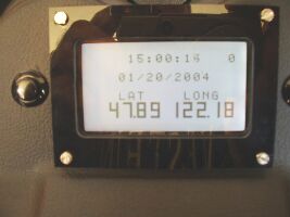
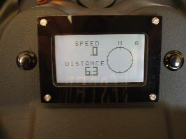
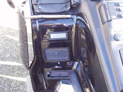
So here’s the current display and the current screens. There
are three screens and two control buttons, the button on the left
selects one of the three screens. The button on the
right is for resetting the odometer.
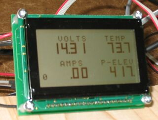
In
the first two pictures above, the zero in the upper right hand corner
is the number of satellites used for the current readings. The number
in the picture is zero since I was in the garage at the time. I
normally get 6 to 9 satellites when riding. In the second picture,
there would be a direction arrow indicating the current direction once
you were moving. Overall I have been quite pleased. The measurements
seem to be very accurate and I can see the display in any light
conditions, even bright sunlight.
Technical
Details
Version 1.0
For my first attempt, I decided I would use a
controller with
analog inputs and an LED display. I chose an Atmel AVR ATmega8
controller since I was familiar with them and had a programmer and the
programming tools. I would use a simple resistor divider for voltage
measurement, an Amploc
AMP50 for current measurement, an LM34CZ
for
temperature measurement, and an MPX4115A
for pressure sensing for
altitude measurement. I also chose to use an OPA2340
op amp
to
buffer the voltage and current signals to keep any spikes out of the
ADC. For the display I used 5 seven segment LEDs from Digikey
and
drove them with a MAX7219
LED display driver. I also used an
RBO40-40T
to protect my circuits from the nasty spikes often found in
vehicle electrical systems.
The
voltage, current, and temperature measurements were all linear and easy
to convert to real world numbers. The relationship between
pressure and altitude is not linear so I used a 450 point lookup table
in the program and interpolated in-between points. This
method
worked well and the results were never more than 10' different from the
result derived from the appropriate formula. Unfortunately,
since
the pressure is affected by the constantly changing atmospheric
pressure, the overall results could be off several hundred feet.
Here are the two boards. The board on the left has
the mega8 and all of the sensors and sensor conditioning and the board
on the right has the LED driver chip along with the LEDs.
Version 1.1
This next version is the one that I had installed in
the bike for 3 years and about 30,000 miles and worked great the whole
time. Since the sensor board worked great -
with the exception of the errors in elevation caused by the changing
atmospheric pressure - and since I didn't want to start all over again,
I decided to retain the sensor board and design a new board.
This
new board would interface with the existing sensor board, the new LCD
display that I had chosen, and the GPS board that I would be using.
The new board mounts directly to the display and contains an ATmega
8535 to control the display as well as communicate with both
the sensor
board and the GPS board. It also contains power supply and
conditioning as well as headers to connect to the sensor board, the GPS
board, and the two pushbuttons for controlling the display.
Here are pictures of the display board. The left
side is the component side of the board and the right side is the
display side.
Version 2.0
Well my Ebay OEM GPS board failed this winter while we were in Yuma and
I
needed to do something different. I looked around a little to
see if I could find another GPS board like the one I have been using.
I couldn't find one and decided that I needed to go with a
GPS unit that was more readily available either for myself or anyone
else that wanted to copy what I was doing. After some
research, I decided on a Garmin
GPS 18 LVC
which is an OEM GPS unit that is basically a small, sealed puck that is
powered by 5 volts and communicates using a 5 volt, RS232 serial
protocol to transmit either standard
ASCII NMEA messages or proprietary Garmin messages.
At the same time, I decided I should use this opportunity to address a
few
other issues. When we are on a trip, I have been using a
Forerunner
GPS to record our route each day. While this
worked, it was a lot of extra effort to download multiple files each
evening, combine them, and convert them to the appropriate form.
It also required extra cables, download adapters, and special
programs. I also had no way to track temperatures during the
day other than to watch the display and remember highs and lows.
Since I now had a GPS that provided route information, as
well as a temperature measurement - all I needed to do was add logging
capability to something like a standard SD
card. So that's
what I did. I retained the sensor board, redesigned the
display board so that it talked to the standard GPS, as well as
provided a serial output port for logging, and designed a simple logger
that accepted commands from the display board and logged information to
an SD card. This way, I could log GPS trackpoints and
temperatures all day long and then remove the SD card at the end of the
day and upload the information to my laptop.
So what changes did I make to the display board:
- The mega8535 was just about filled up so I needed to add a
new processor. Even though a mega16 would have been more than
sufficient from a memory standpoint, I chose a mega324p
since it had 2
UARTs. I could use one to communicate with the GPS and the
other to communicate with the data logger. I could have
gotten by
with a mega164p but the 324p was only about a buck more and gave me
twice the memory to implement future features.
- Although the serial output from the GPS was 5 volts which
would be compatible with the mega324p UART,
it was designed to interface with a PC so it was inverted relative to
the UART on the
mega324p. This meant the addition of an inverter and I chose
an SN74LVC2GU04DBVR.
This is a 2 channel inverter (one channel for send and one
for receive) in an SOT23 package.
- I decided that I would use standard RS232 to communicate
with the data logger so that both the display board and the logger
would be more or less standard and provide more options for future
expansion or
changes. This required adding an RS232 transceiver and I
chose a Dallas/Maxim
DS275. These are great little 8 pin
chips
and very easy to use - I have used them frequently in past projects.
- I wasn't entirely happy with the headers in my last board
so I added new headers
with locking ramps to make sure they stayed in
place.
- I wanted to be able to turn off the display backlight to
conserve power so I added a transistor to control the backlight.
I could also use this in the future to vary the backlight
brightness if I choose to do this.
- Finally I used more SMD components. They take up
significantly less board space and are pretty easy to use as long as
you don't go ridiculously small. I'm finding I like using
these more and more.
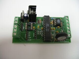
Here are pictures of the new display board:
 |
 |
And here are the schematic and PCB for the display board:
 |
 |
The logger ended up being fairly simple. It included another
mega324p, power supply, SD card socket, an RS232 transceiver, and LEDs
for status. I used the mega324P since I was already using the
same processor on the display board and I would again use both UARTs.
The first UART would interface with the display board and the
second would output diagnostic messages for debugging and
troubleshooting. I used an SD card since Bascom,
that I would
be
using to program the logger, has a built in library - AVR-DOS - to
simplify interfacing with all types of storage devices. Since
SD
cards operate on 3.3 volts, I added a 3.3 volt power supply and
associated passives. I used a Sipex
3232E transceiver since
it
would operate at 3.3 volts and provided an interface for both UARTs.
Finally I added 3 LEDs for status - one indicates that a card
is
inserted, it is not write-protected, and it has initialized correctly,
one indicates that the card is ready, and the third indicates a write
in progress.
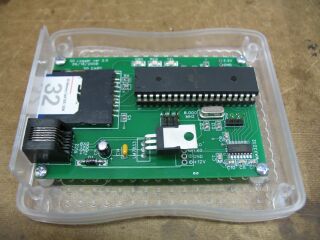
I found a nice
case at Spark
Fun Electronics.
It's clear so that it would be easy to see the LEDs, and has
a
clever mounting feature for the PCB built into the case. I
cut
2
openings in the case - a slot for the SD card and an opening for the
RJ11 jack that I use to connect the logger to the display board.
This makes it very easy to disconnect the logger or remove
the SD
card.
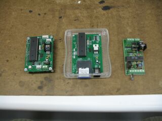
Here are pictures of the logger board and all 3 boards:
And here are the schematic and PCB for the logger board:
The GPS is configured to output standard NMEA messages. I am
currently only using the GGA and RMC messages since these provide
everything I need. These messages are logged to the SD card
every 4 seconds along with the temperature. This file can be
read directly by RoboGeo.
I use RoboGeo to create Google maps
and geocode pictures and place markers on the map. Here's a
sample of a log file and
here's a page
with a Google map and pictures. I also have a
simple VB program that can extract each of the messages in the file to
its own file. This way I can import these files into Excel
and graph any of the information being logged. I can't wait
to use it on my next trip.
Thanks for visiting and feel free to email
me
with questions or suggestions. I can also provide TinyCAD
schematic, FreePCB pcb, and Bascom files if anyone is interested.
After several requests, I have posted the Bascom source files for all
three processors, you can download them from the link below.
Home