Table Saw Blade Height Readout
Background
As a part time woodworker
(and not a very accomplished one at that) I'm always looking for ways
to improve my accuracy and precision. Along those lines I
have added an Incra
TS III Fence to my Jet 10"
contractors saw, a Wixie
Digital Readout for blade
angles, and numerous home
made jigs
and fixtures all in my quest for
more accuracy. The Incra fence has been a great addition due
to its excellent accuracy and repeatability. What I was
missing was an accurate way to measure and set the height of a saw
blade above the table. Like most table saws the blade height
is
set with a hand crank that controls a worm gear/spur gear segment
arrangement that raises the blade by pivoting the arbor arm.
While the system works, there tends to be backlash in the
gears
that makes it difficult to set the height accurately and it's easy to
overshoot. Then you have to come down below the desired
setting
and raise the blade back up again. Although you can measure
the
height with a ruler or height gauge, you still need to make a trial cut
and then measure the cut to check for accuracy. You can
adjust
out some of the gear backlash but, if you get the gears too tight, they
will bind up. I could not find a commercial unit to
accomplish this task so I set out to design my own.
Sensor Selection
I tried various sensor approaches including linear pots,
rotary
pots, even an LVDT. I also looked at cheap digital calipers
and
some of the sites for hacking them to read the values with a
microcontroller. One of the problems is that the saw blade
arbor
pivots
on
an axis, most of these sensors read a linear distance, and the height
change is not linear with the rotary movement of the arbor. I
considered an encoder attached to the pivot point but that became a
complicated mounting problem. I finally
settled on using an accelerometer attached directly to the arbor arm.
Besides measuring acceleration as the name implies, an
accelerometer is also a very good device for measuring tilt.
After some research, I chose an Analog
Devices ADXL202e.
The guts of this accelerometer consists of a mass suspended
by
polysilicon springs that deflects when the chip is subjected to a
positive or negative acceleration. The deflection of the mass
moves a central plate between two fixed plates and changes the
capacitance of these plates. The electronics of the chip
ultimately produce a duty cycle modulated wave, the frequency of which
changes with acceleration. The signal looks like this:
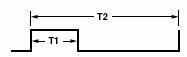
where T2 represents the frequency of the signal and T1
represents
the amount of acceleration or deceleration or, in our case, tilt angle.
When the chip is level, the duty cycle is approximately 50%
and
then increase or decreases as the chip is tilted. By changing
a
single resistor, you can change the complete cycle frequency of the
output from 0.5 ms to 10 ms. I chose to use the longest
frequency since speed was not critical and I wanted to get
the
most
resolution that I could. So, in the figure above, T2 would be
10
ms and T1 would be proportional to the tilt angle.
Reading The Sensor
Now that I had a sensor, I had to have a way to read it and
display the results. I have been playing around with Atmel AVR
processors for a while now and so I decided to use an Atmel ATMEGA8
microcontroller. The plan is to start the internal counter in
the
processor and then count the number of counts for the T1 part of the
cycle as well as the entire T2 cycle. Then dividing the T2
counts
by the T1 counts gives us the duty cycle of the output. This
should be proportional to the saw blade height. I decided to
use
a simply 2 line by 16 character LCD
display since they are inexpensive, readily available, and
easy to interface. I also planned to use Bascom
for the programming. Bascom is a very full featured Basic
compiler for the entire AVR line of controllers.
I
used an 8.000 mhz crystal on the processor and a prescale of 8 on the
counter. With that combination, I should get one count every
microsecond and 10,000 counts during the 10 millisecond period.
In the real world I consistently read about 8350 counts.
I'm not sure what the discrepancy was - it may be processor
the
crystal, the accelerometer itself, the resistor used to select the
period, or the fact that I was using basic instead of assembly
language. The important part is that the count was very
repeatable which is what was important to me. I did find that
the
output of the accelerometer tended to vary with ambient temperature so
I added temperature compensation to improve the accuracy of the reading.
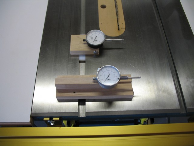
Once
I attached the accelerometer to the saw arbor and began to take
readings, I found that the saw height was in fact linearly proportional
to the blade height. This worked out great and made it very
easy
to calibrate the output.
Putting It All Together
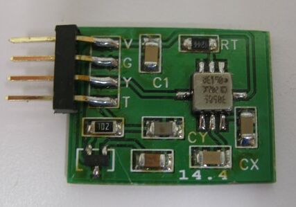
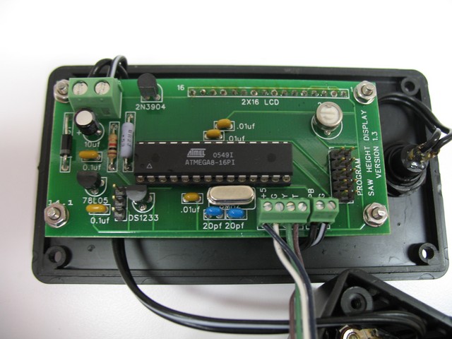
I ened up with two printed circuit boards. One has the
accelerometer, the temperature measuremnt device, and a few resistors
and capacitors. The other board has the main processor, the
display, a programming header and other support chips. Here
are
the two boards assembled and ready to go:
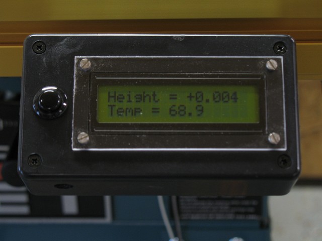
The display looks like this after being assembled:
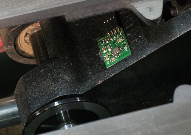
I attached the accelerometer board to the saw arbor using hot melt
adhesive and it looks like this:
Finally the finished product looks like this:
Using the Readout
Using the new readout couldn't be easier. When you first turn
on the readout or when you change blades, simply crack the elevation
until the tip of the blade is level with the top of the table and press
and hold the button for a second. This saves the current tilt
and teperature in EEPROM and becomes the new baseline data.
Then, as you crank the elevation handle, the new height is
read out on the display. If the device is left on for 30
minutes or so, the backlight will be turned off. Pressing the
button with the backlight off will turn on the backlight but will not
reset the calibration data. Of course pressing the button
with the backlight on will reset the calibration data in EEPROM.
Turning the display on with the button pressed will display
the calibration data for 10 seconds and then revert back to the normal
display if the button has been released. If the button is
still pressed at then end of 10 seconds, debug mode will be entered in
which more base data is displayed.
Programming
As mentioned before, the programming was done with Bascom and is fairly
well documented. Basically the program consists of a main
loop that takes 50 accelerometer readings, averages them, takes 50
temperature readings, averages them, and finally computes the current
height and displays that value on the LCD. There is nothing
very special about the program and it should be fairly easy to change
or modify. There are two constants that may or may not need
to be changed. They are Tempcal and Heightcal. The
Heightcal is basically the change in % duty cycle per inch of blade
travel and is currently set to 278. This represents a
theoretical resolution of about .0036". The Tempcal value
represents how much the temperature change affects the final reading.
The current value is 10 and represents a 10% contribution for
the temperature change in 0.1 F. I haven't tried different
accelerometers so I don't know if these values work in all cases.
Final Thoughts
So am I happy with results - definitely. Is the readout
perfect - no. There is some slight variation. If I
watch the readout it varies .003" to .005" or so but if I come back in
2 or 3 days, the readout is still within the same range. I
suppose I could get better repeatability and a more stable display if I
implemented a different averaging technique but that may take longer to
stabilize and the current method is plenty good enough for me and way
better than I had before.
Software and Files
I am providing all of the files in case anyone wants to build one of
these readouts. The link below will download a zip file that
contains schematics for both boards in pdf and TinyCad
format, PC Board files in jpg and FreePCB
format, Gerber files for both boards, and
the Bascom
source and hex files for the processor. I hope you
enjoy this project as much as I have.
Version 2.0 - 5/15/13
Since my first version of this device, I
have learned a lot more about Bascom and AVR programming - specifically
in the area of interrupts. So it seemed like a good time to revisit my design and upgrade the software if possible.
I
started by making several hardware changes although none of them
required changing the PCB design. The first change was to switch
to an Atmega88 since the Atmega8 is now obsolete. I changed the accelerometer to an ADXL212 since the ADXL202
is now obsolete and the new accelerometer is less temperature
sensitive. I also changed the 1.2 Meg resistor that sets the
period of the accelerometer signal to a 1.0 Meg resistor. This
shortens the period to slightly less than 8 ms which allows us to
use a prescaler of 1 and not get a wrap around on the 16 bit timer
during one period.
From a software standpoint, the new program
sets up a pin change interrupt on the processor pin connected to the Y
axis of the accelerometer. In the interrupt routine, we determine
where we are in the period and calculate the number of timer counts
lapsed since the last interrupt. We average the values over 128
readings which gives us an update rate of about once per second.
I also round the result to .005" which seems to be fine for my
woodworking projects. The result is very stable.
Besides
the zero routine which I left the same, I also added a calibrate
routine. If you hold the button down while powering up the board,
you will go into the calibrate routine. This asks you to set the
blade to zero and press the button and then raise it to a 1" height and
press the button again. That completes the calibration and the
factor will be saved to EEPROM and the program returns to normal
operation.
The new Bascom program is included in the download file above.
Questions
or Comments
Home