
I have added several cameras to my home control system and
plan to
add more in the future. I also added an ASELPRO
Video Switcher
from National
Control Devices.
This is a 16X2 switcher so it
gives me plenty of room for expansion. While the cameras are
nice, what I really wanted was the ability to pan and tilt selected
cameras to change the view if necessary. I did quite a bit of
searching and most of the pan and tilt mounts were more than I was
willing to pay. I also considered building my own but, while
doable, was more packaging than I wanted to mess with. I
finally
settled on the Ninja
Pan and Tilt Camera Mounts from X-10. These
are relatively inexpensive - I got my last one on eBay
for $30 - and
appear to be reasonably well built.
The negative to these mounts, at least for me, is that they
are
controlled by an RF remote and the knock on them is that they have a
pretty limited range. My cameras tend to be spread out and I
wanted to control them from my home control system located in the
basement so that didn't seem to be a very attractive option.
There are quite a few sites around the internet devoted to hacking
these devices but most of them seem to be aimed at increasing the range
of the remotes. There's even a few where someone has replaced
the
processor in the Ninja with their own processor and custom
code.
Since my cameras are all hard-wired, I decided to go with a hard-wired
approach for the Ninja as well and convert them to operate an an RS-485
network. That's what this page is all about.
As I mentioned previously, there is quite a bit of information
available on the web and the most important piece of information I
needed was the protocol currently used by the Ninja. I found
the
best descriptions on Ed
Cheungs comprehensive home automation site (although the data
was
actually provided by Dennis Hawkins) and Dave Houston's
excellent
web site. I also found all of the details of how
the Ninja
hardware worked on this site. This last modification
consisted of
replacing the micrcontroller with an SX controller and changed the
Ninja to be controlled over a serial link to a PC. It also
involved a new protocol and several new capabilities. While I
liked this approach, I wanted to control several Ninjas and the
distance would just be too great for an RS-232 connection. So
let's get started.
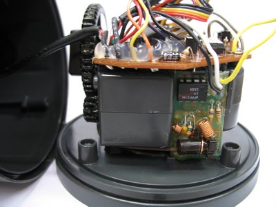
Here are a couple of shots of an unmodified Ninja disassembled
to
see the guts:
 |
 |
In the shot on the left you can see the PCB, main processor,
the 5
volt regulator under the mess of wiring, and the ribbon cables which
supply the power signals to the servos located under the PCB.
In
the shot on the right you can see the RF receiver board which is
responsible for receiving the RF signal and transmitting it to the main
processor. This board has 3 wires connecting it to the main
board
- the white and black wires which are +5V and Ground as well as the
yellow wire which is the signal to the main processor. Since
we
are not using RF, we will remove this board and then design our new
interface to fit in the same location using the same wires.
If we
do this correctly, the processor will never know the difference.
Before removing the board completely, I cut the wire to get a
better
look at the signal going to the Ninja processor. In order to
see
this, I used my Logic
Analyzer
from Saleae LLC. This is a great
product at a great price and, if you've never used one before, it's a
great tool for understanding whats going on with your circuits and
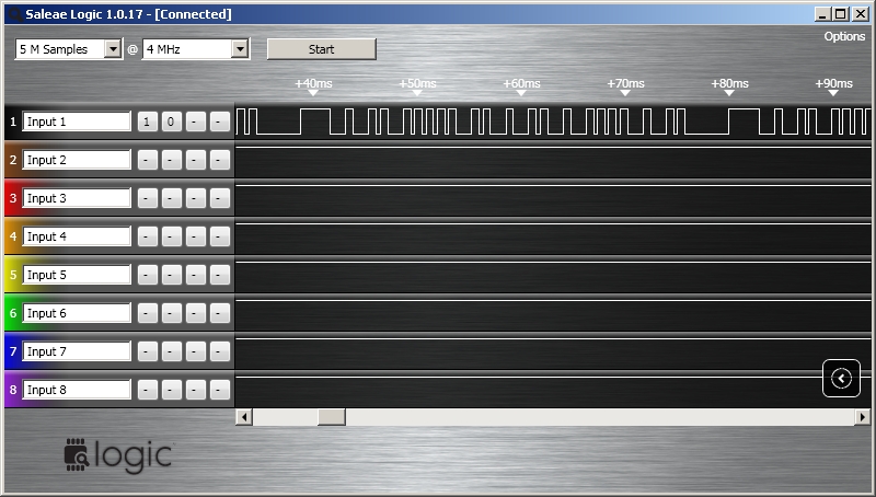
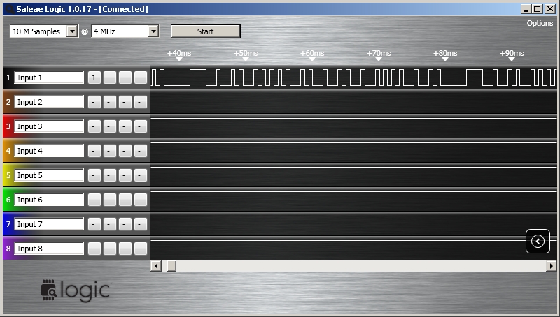
programming. So when I hooked up the analyzer to the yellow
signal wires, here's what I got:
If you look at the detailed
protocol
documents, you'll see that this matches the described protocol
extremely closely. Now I knew what I had to produce.
 |
 |
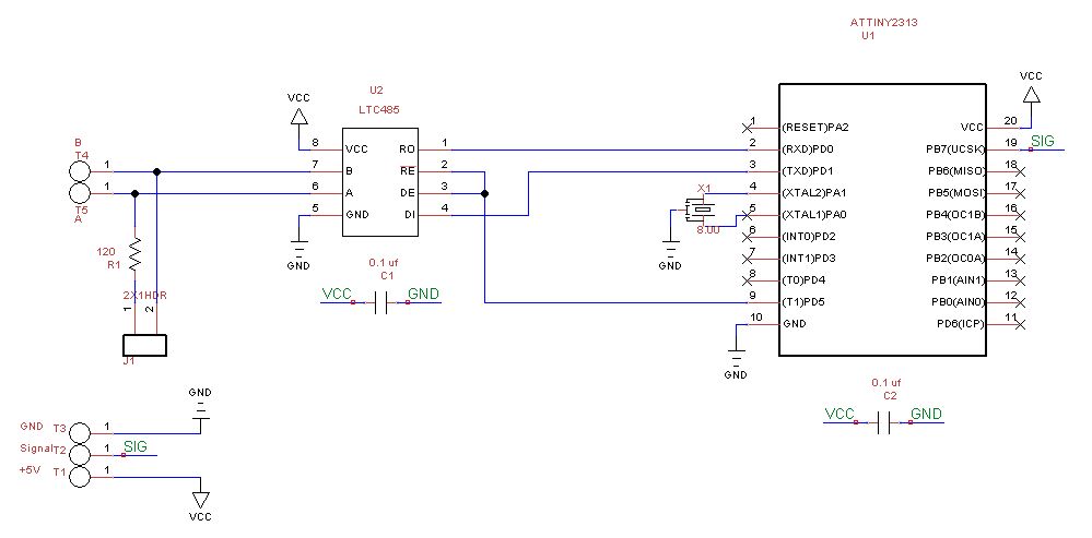
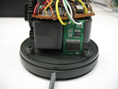
The board fit perfectly and here's the Ninja with the new
board
installed:
 |
 |
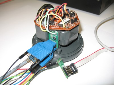
The only problem I had was that there was no room left on the board for a programming header which I try to put on all of my AVR boards. Since this was also my first surface mount AVR, I couldn't use a piggy-back type board in a socket to do my programming like I have done in the past. The solution was a Pomona SOIC Clip. I had a little problem getting this to work in the beginning but only because excess flux from the my soldering was causing contact problems. Here's what the clip look like in actual use:
So now I had my hardware modifications made. Before I go on
to
the software, a few more explanations are in order. The Ninja
is
powered by a 12 volt, 200 ma, X-10 controlled plug-in supply.
Although rated at 12 volts, the supplies are poorly regulated and the
ones I checked actually measured around 22 volts.
The power
supply has 3 wires going to the Ninja. Two wires provide the
operating voltage and are
active all of
the time. The third wire carries power only when
the X-10
address of the power supply is on. This tells the Ninja that
it
is being addressed and to respond to move commands. As far as
I
can tell, although there are separate commands for each home address
(A, B, C,...), the Ninja will respond to any of them if its signal lead
is powered.
Doand the Sendcmd subroutine looks like this:
'wait for address
Do
Do
Ch = Ischarwaiting()
Loop Until Ch = 1
Get #1 , K
K = K - 48 'convert from ASCII "0"-"9" to 0-9
Loop Until K = Myaddr
'now wait for command
Do
Ch = Ischarwaiting()
Loop Until Ch = 1
Get #1 , K
Cmd = Chr(k)
'this must be for us so see if it matches one of the possible commands
'and set up values for A and B for that command before calling subroutine
'to send command
A = &H0000
Select Case Cmd
Case "l" : A = &H9560 'left
Case "r" : A = &H9661 'right
Case "c" : A = &HA16C 'center
Case "u" : A = &H9762 'up
Case "d" : A = &H9863 'down
Case Else
End Select
B = &H0006 'always
If A <> 0 Then 'we have a valid command
For K = 1 To Rpt
Gosub Sendcmd
Waitms 10
Next Rpt
End If
Loop
'**********Ninja command protocol**********
'The start sequence is a 2.4ms pulse followed by a 1.6ms space. A 1-bit is a
'0.6ms pulse followed by a 1.6ms space and a 0-bit is a 0.6 ms pulse followed
'by a 0.6ms space. Only 20 bits of data are sent. A 0-bit marks the end of
'the frame. Repeats follow with no gap.
'See: http://davehouston.net/cr14a-rf.htm
Sendcmd:
 Reset Signal
 Waitus 2400
 Set Signal
 Waitus 2400
 Reset Signal
 Waitus 1600

 For I = 15 To 0 Step -1
 Set Signal
 Waitus 600
 Reset Signal
 If A.i = 1 Then
 Waitus 1600
 Else
 Waitus 600
 End If
 Next I

 For I = 3 To 0 Step -1
 Set Signal
 Waitus 600
 Reset Signal
 If B.i = 1 Then
 Waitus 1600
 Else
 Waitus 600
 End If
 Next I

 Set Signal
 Waitus 600
 Reset Signal
Return

End

