Current Sensor
Background
For a while now I have wanted some type of current sensor for
use
with my Homevision home control system. Originally I wanted a
device to indicate when a television was on since most remote controls
just toggle the power on a TV and don't know if the TV is off or on.
I tried several video sensors but I couldn't get any
of
them to operate reliably. I sort of lost track of the effort
until recently when I need some way to track the hours on my air
compressor to know when it was time for service and on my furnace to know
when it was time to change filters.
So I decided to design a current
sensor which would be simple, reliable and easy to interface to my
Homevision controller. Before I go any further I have to say
that, although I have quite a bit of experience with industrial
electrics, I am not an electrical engineer. All of my
knowledge
in this area is self taught. So I'm not guaranteeing anything
and, if you decide to build any of these, you do so at your own risk.
All I can say is that they work great for me.
Design
The design uses a Coilcraft CS60-101 current trransformer
which
basically converts the current in a wire passing through the center of
the coil into a voltage. Although this voltage is quite
small, it
can be amplified and then rectified to get to a useable voltage level -
and that's just what I've done. Here's the circuit diagram:
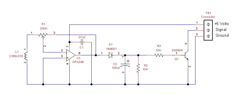
The voltage created by the coil in the above drawing is amplified
through the OPA340 op amp based on the ratio of R2/R1. In the
drawing, R2 is the resistance between terminals 2 and 3 of the 200K pot
and R1 is the resistance between terminals 1 and 2. By
adjusting
the pot the gain can be adjusted over a wide range. The
output
voltage from the amp is half wave rectified by diode D1 and smoothed
out by the 100uf capacitor. Resistor R2 pulls the base
of transistor Q1 to ground preventing it from conducting.
When the voltage at the base of Q1 exceeds approximately 0.6
volts, the transistor will conduct and the signal from the controller,
which is normally pulled up to 5 volts, will be pulled to ground and we
get a change on the controller input signal which is connected to
terminal 2 of TB1.
Results
So far I have been very pleased with the results. I can
easily
adjust the potentiometer to the point where there is no change on the
input port until the device is turned on and then the input port
changes from 1 to 0 signalling the controller to take an action.
I have successfully used this sensor on loads from
approximately
300 ma to as high as 15 amps. Although the coil is only rated
to
10 amps, using it on loads up to 15 amps caused no problems.
The
other nice thing is that the load on the controller is only about 1 ma
- easily within its range to provide power.
Here's a few pictures of the sensor.
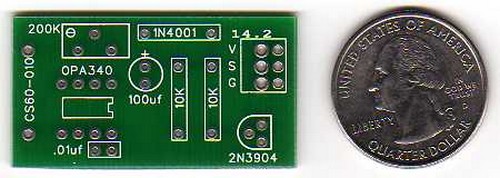
First the bare board:
Board fully populated:
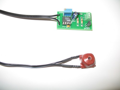
Board with sensor:
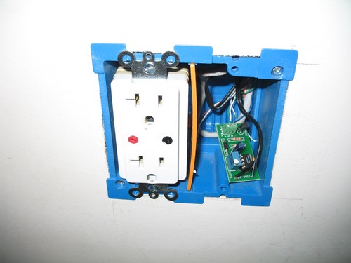
Board installed:
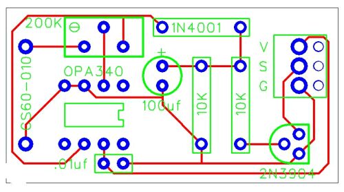
Finally PCB layout:
I also have links to images of my air compressor runtime tracking page and my furnace fan runtime tracking page.
I am also providing all of the files in case anyone wants to build one
of
these sensors. The link below will download a zip file that
contains a schematic for the board in jpg and TinyCad
format, a PC Board file in jpg and FreePCB
format, and Gerber files for the board. I hope you
enjoy this project as much as I have.
Questions
or Comments