Digital Planer/Sander Gauge
Background
As part of my woodworking hobby, I had acquired both a Dewalt
DW733
portable thickness planer and a Performax
(now Jet) 16/32 drum
sander over the years. Both tools are fine but I have always
wished for better, more accurate thickness control. I use a
set
of calipers to measure board thickness after a pass but the actual
measurement
scale supplied on each tool is just a moving pointer on a fixed scale
so it can
be difficult
to get consistent, repeatable results. Wixey
makes a digital gauge that I
could purchase and install but what fun would that be.
Besides I
wanted a gauge that I could program to work the way I wanted it to not
the way someone else wanted it to. It would be ideal to
basically
attach the calipers I was using directly to the machine. I
had
seen numerous sites
over
the years that covered hacking and interfacing an inexpensive digital
caliper and thought that this might be a good way to go.
I use
several different sleds and jigs on both machines so a gauge which I
calibrate once and then don't have to calibrate again wouldn't quite
meet my needs. Wixey has a relative mode where you can
measure
your board, subtract the desired thickness from the measured thickness,
set the gauge to zero and then adjust the machine to remove the
required amount. My plan was to measure a board, set the
gauge to
the measured reading, and then, as you adjust the machine, the readout
will read the actual board thickness.
Hardware
As I mentioned above, my plan was to use an inexpensive
digital caliper like the kind they sell at Harbor
Freight.
The calipers are made in normally China and you can buy them
numerous
places. There are also numerous web sites which have detailed
information about hacking these calipers. I have actually
seen
them on sale at Harbor Freight for as little as $10. Here's
what mine
looked like:

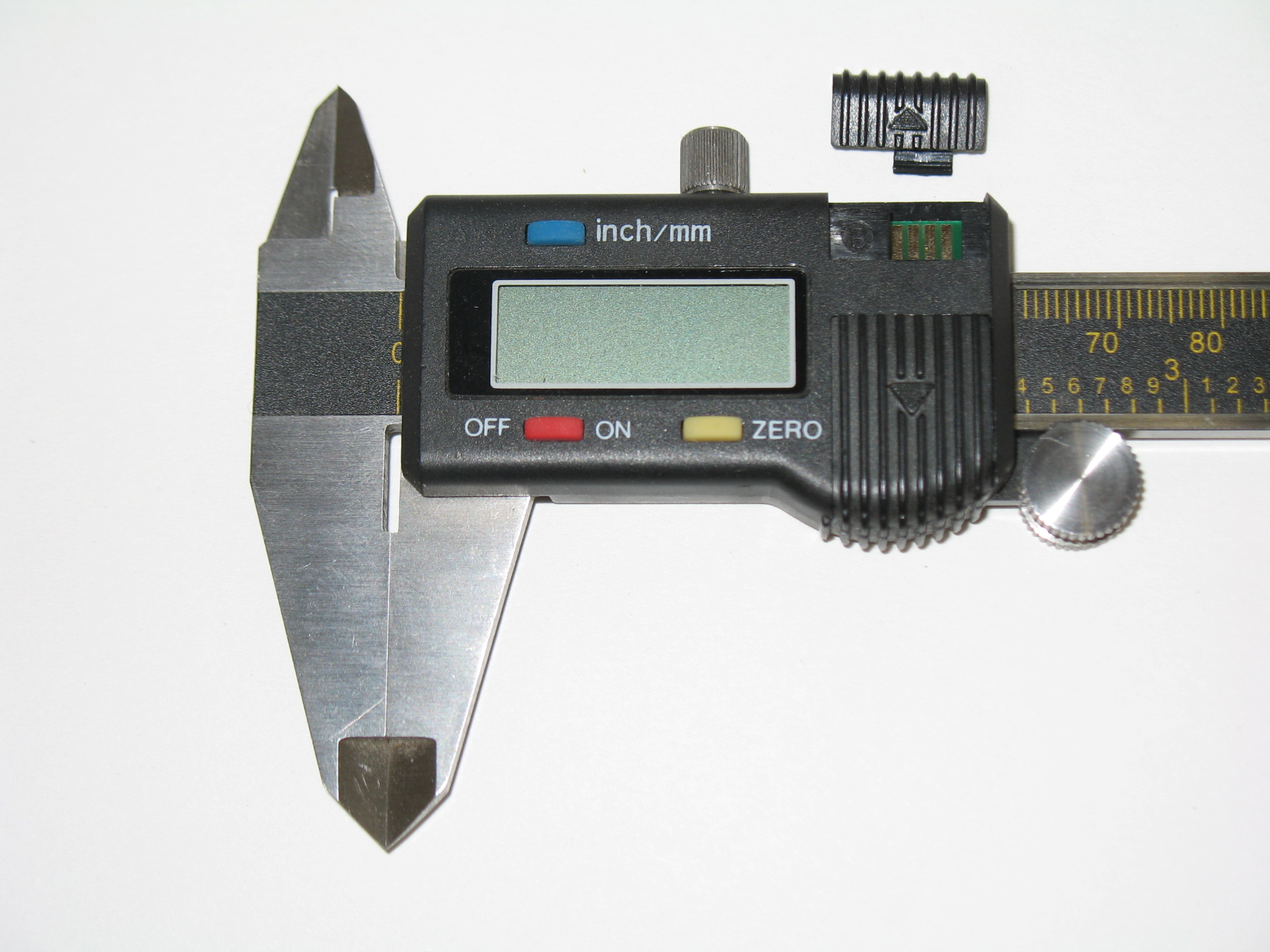
The interesting thing about these calipers is that they have a
small,
sliding window that, when opened, exposes 4 connectors on the circuit
board that provide an interface to the caliper and its readings.
The interface looks like this:

The
4 connections are ground, data, clock, and 1.5 Volts from left to
right. The data is clocked out on the data pin about every
300 to
330 ms and is composed of 2 - 24 bit numbers that represent an absolute
position and a relative position since the last time the caliper was
set to zero. The numbers are in 1/20480ths of an inch.
There are a number of web sites that probably explain the
protocol much better than I could and I provide a link to many of those
sites at the bottom of this page.
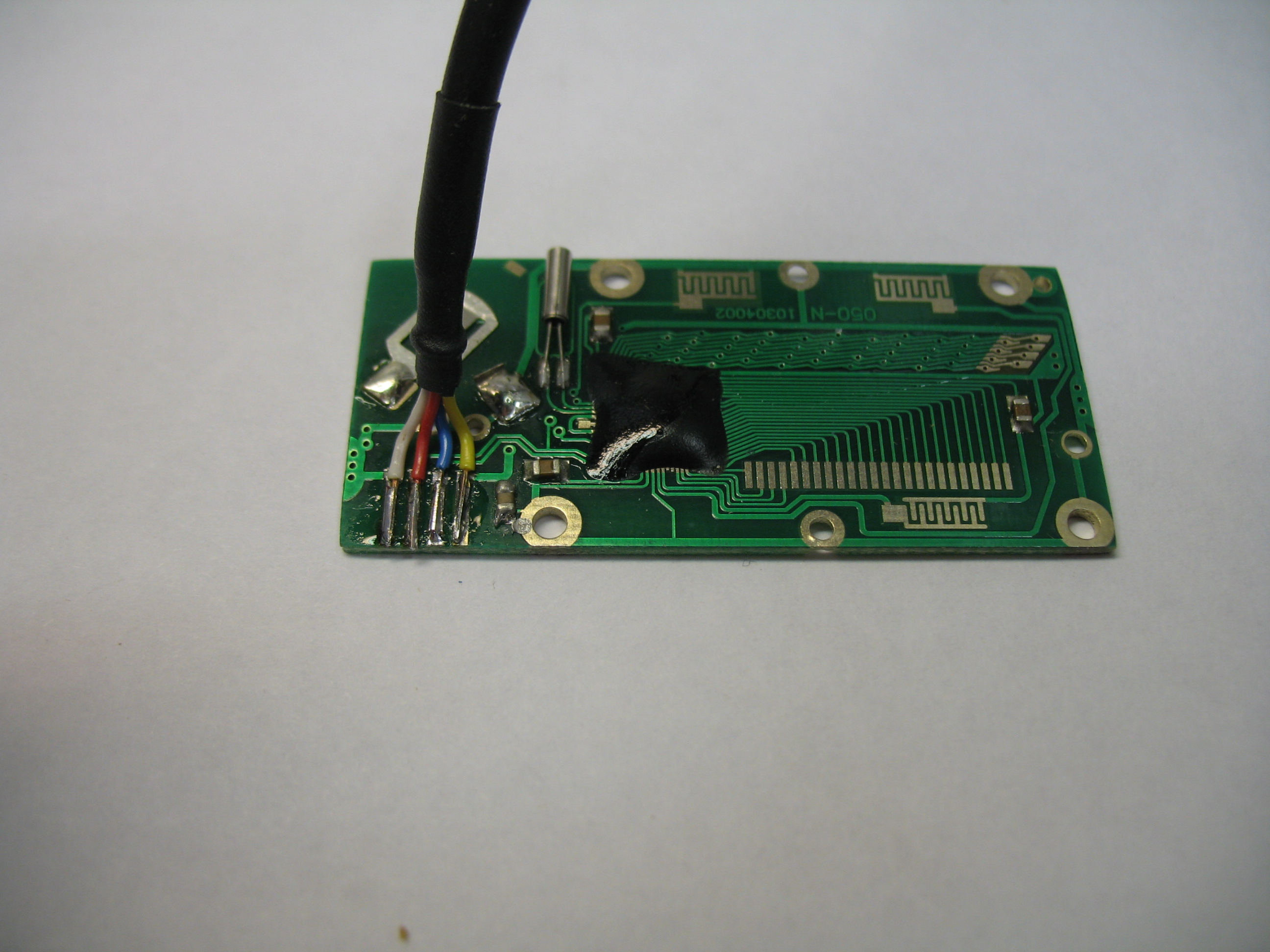
I also needed a cable to connect to the caliper and Little
Machine Shop
sells just such a cable. The problem is that there really
doesn't
seem to be a mechanical standard for the caliper housing and they are
not all the same. I have three of these calipers and the
cable
only worked really well on one of them. My solution, which I
also
found on the Internet, was to solder the wires directly to
the
circuit board and provide a simple strain relief. The idea
and
detailed instructions for this modification are provided on this web
site
(which is in German but translated here into English) and worked really
well. This is what my circuit board looked like with wires
attached ready to re-assemble:

Finally
I made several modifications to the calipers themselves just to
simplify
mounting for my application. I added 2 - 1/4" X 3/16"
bushings and planned to mount them on my machine with a pair of 3/16"
shoulder screws.
Unfortunately I ignored the fact that the calipers are positive
ground (in that the +1.5 volts is connected to the frame of the
calipers). For that reason they needed to be isolated from the
metal frame of the machine so I ended up mounting the calipers with
nylon hardware. This would be optional and may not be necessary
at all
depending on your application.
Here's my completed calipers ready to go:

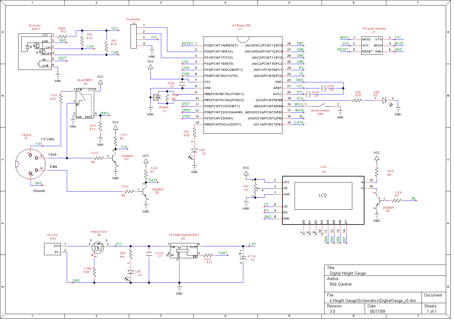
The
final piece of the system is the interface itself. I chose to
use
an Atmel AVR micro to interface with the calipers - specifically an
ATMEGA168. Most of the information I found on the Internet
related
to using PIC processors so this is the first AVR implementation that
I'm aware of. The program only uses 19% of the processor
memory
so a
smaller processor would work but I wanted room to grow and I only stock
2 or 3 different processors since the cost difference for a one-off
application is nominal. Here's the schematic for the
interface,
you can click on it for a larger view and the files are available for
download at the bottom of this page:

There
are several interesting things to discuss here. As I
mentioned,
the processor is an ATMEGA168
running at 8 Mhz. I probably could
have gotten by using the internal oscillator but I chose to add an
external resonator. Although I'm not currently using it, I
added
a header for RS232 serial communications in case I needed it in the
future and the internal oscillator is not always accurate enough for
reliable RS232 comms. I'm using an external 5
volt
regulated wall wart
so no need for a 5 volt regulator but I do like to provide reverse
voltage protection to my projects and that presents a minor problem
since the normal method is a
blocking diode but that would lower the 5 volts to only about 4.4
volts.
The solution was to use a PMOSFET
in an unusual configuration. Rather than a detailed
explanation, here
and here
are two sites where I got the idea and that explain this use much
better than I could.
The calipers require 1.5 volts so I used a TI TSP769 series LDO
regulator. This regulator also has shutdown capability.
I have connected this pin to a processor output pin but am
not currently using this feature. The problem with 1.5 volts
on the
caliper volts is that signals from the clock and data pins are also 1.5
volts and, since I'm running the processor at 5 volts, the Mega168 data
sheet specifys the input port high voltage needs to be a minimum of
0.6Vcc - that means I need a minimum of 3.0 volts to recognize a high
signal. I solved this problem by using a 2N3904 NPN
transistors with appropriate resistors on both the data and clock
signals.
This has the effect of boosting the high voltage to 5 volts
and also inverting both signals. This doesn't really bother
me since I can compensate for the inversion in software if necessary.
You can also see an NLAS4501
analog switch that can connect 1.5 volts to the clock pin through a 10K
resistor. This can be used in software to zero the calipers.
There is also quadrature encoder with push button switch
which provides the user interface to the caliper gauge. This
is connected according to the encoder
data sheet.
Finally there's a Crystalfontz
LCD to display the readings and three LEDs - one for power
on, one for mode display, and the final one is a heartbeat signal that
is toggled every time a new reading is received.
Once the schematic was designed and tested, the next thing was a PCB to
build the interface. Here's the designed and the completed
PCB:


I designed the board using FreePCB
and purchased the board through
BatchPCB.
I have used both of these for several projects now
and have been very pleased with the results. I also used an
enclosure
from SparkFun. I have used these enclosures before
and I like the size and the fact that they are clear and you can see
your project and any LEDs you might have. Here's the
populated board and the finished enclosure:


Finally, here are all of the pieces together:

Software
The software is written with Bascom
AVR from MCS Electric.
I
have been using this software for quite a few years and find it to be
very good, very fast, and easy to use. There are two
modes
in the program - calibrate
mode and measure mode. The main loop in the program checks
the
encoder
pushbutton and, when pressed, toggles between the two modes.
In calibrate mode the software monitors the encoder movement
and allows the user to dial in a measurement which then becomes the
current measurement and all further movement of the calipers are
relative to this value. In measure mode the calipers are read
with each update and this value is added or subtracted from the
calibrate value and displayed on the screen. The current mode
is displayed on the LCD as well as either the set point or measured
value. The current mode is also indicated by an LED on the
board. Both modes are controlled by interrupts.
In measure mode, the clock pin is connected to the Int0 pin.
An actual set of readings only takes about a millisecond so
the software looks for any clock signal then waits 5 milliseconds to
make sure we are past a reading before enabling the interrupt, this
prevents us from starting in the middle of a reading.
Once enabled, the interrupt signals when the clock start
signal is detected and the interrupt routine clocks in the 2 - 24 bit
signals that the caliper sends out using the Shiftin routine.
Each time a new reading is available, the main loop combines
this new reading with the calibrate set point and displays this
combined
reading on the LCD. Here's what a typical reading looks like
on my scope:

The calibrate routine uses several interrupts. The two
quadrature outputs are connected to inputs which are configured as pin
change
interrupts and a separate Timer1 interrupt is also enabled.
The Timer1 interrupt occurs every 65.5 ms and increments a
variable to a max of 5. Each time an encoder interrupt
occurs, the interrupt routine determines the direction of the encoder
and checks the value of the timer variable and, using these two pieces
of information, determines whether to add or subtract to the calibrate
value and how much to add or subtract. Each time the value
changes, the reading is updated on the LCD. Using this
method, if you turn the encoder fast, the value will be increased by
large amounts and, if you turn slowly, the value will be incremented by
a minimum amount. This way you can get to a large number
quickly and then slow down to dial in the exact value desired.
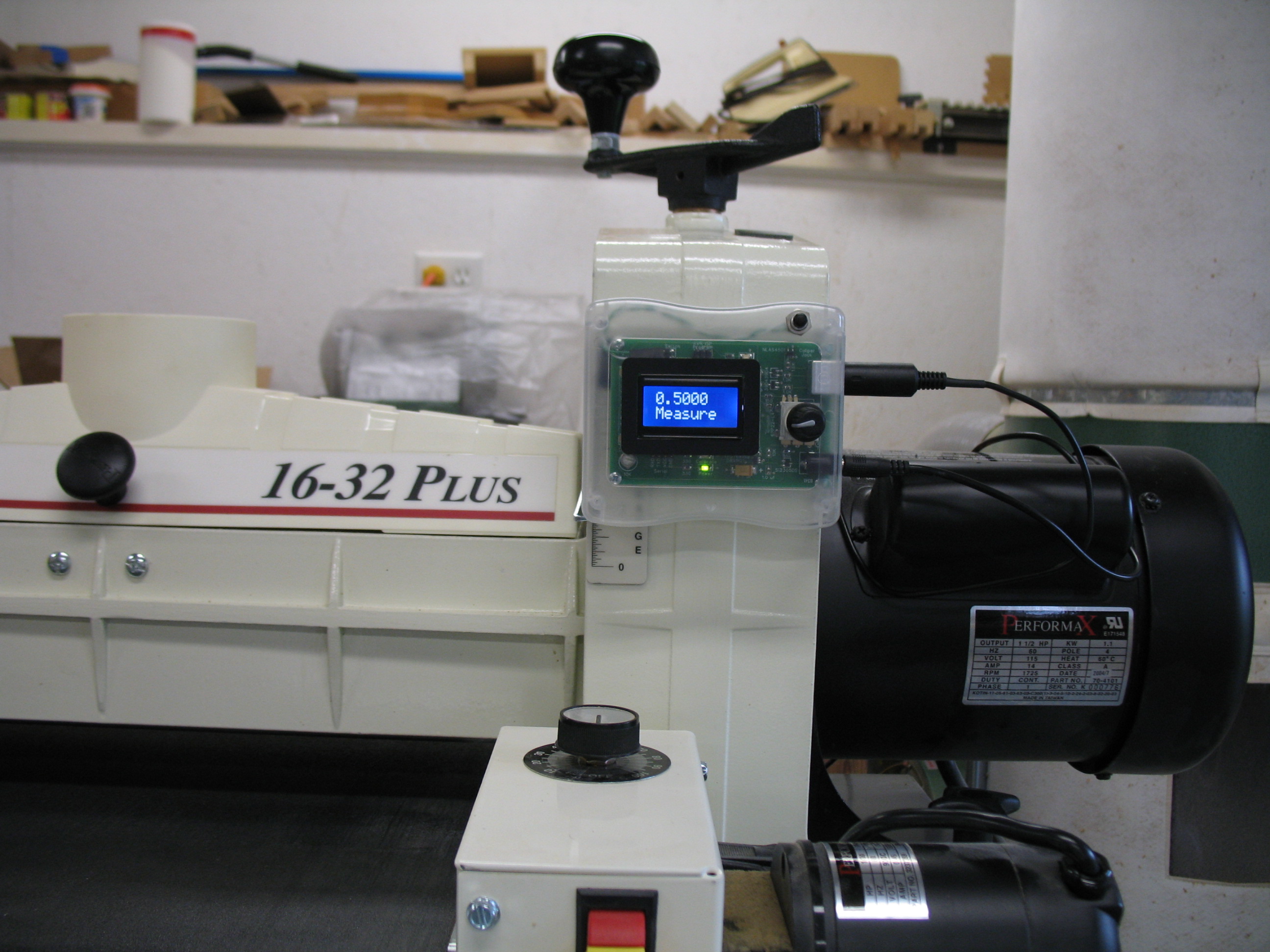
Finished Project
Here are a few pictures of the finished project mounted and in
operation:


Downloads and Future Plans
I'm providing a full download package that includes all of the relevant
files for this project including:
- Schematic in TinyCAD format as well as a PDF file of the
schematic
- PCB file in FreePCB format as well as a full set of Gerber
files
- Parts list in Excel format
- Bascom AVR source file and program HEX file
You can also purchase a PCB directly from BatchPCB.
My next step is make a second gauge and install it on the sander.
In retrospect there is one thing I would probably change if I
started over again. I would probably add a large capacitor
that would keep the voltage up for a few seconds after I powered the
unit down. That way I could detect that the power was shut
off and save the current reading to EEPROM so that I could
make that the calibrate reading the next time power was turned on.
I can accomplish the same thing on this board by installing a
momentary contact switch and saving the reading if I press the switch.
I actually added a two pin header on the current PCB just in
case I wanted to do something like this.
Here are some of the Internet links that I found useful in developing
this project presented in no particular order:
Updated 3/25/10
After a few months of using the new gauge, I decided I needed to make a
few upgrades. I still had a header on the PCB labeled Switch that
I had originally thought of using to change modes until I decided to
use an encoder that had a switch built in. I left the switch
header in case I came up with another use for it. Well I
installed a small NO pushbutton switch and wired it to this header and
programmed the switch to save the current reading to the EEPROM memory
when it was pressed. Then I read that reading from EEPROM each
time the gauge is powered up. Unless I move the planer head when
the power is off to the gauge, the calibration shouldn't change between
uses of the planer.
The second change was to retain the current reading when going into
calibrate mode. Previously the calibrate offset always went to
zero. I realized that more often than not I only needed to make a
minor tweak to the setting and going back to zero each time was a waste
of time. So far I'm happy with the new changes.
This what the gauge looks like now. You can see the pushbutton in
the upper right corner.
I have included the new Bascom source and hex files in the download
package.
Updated 4/13/10
Well, this is embarrassing. I posted the update below after
mounting my new gauge and running the head up and down to make sure it
worked - but never actually running the sander. I ran the sander
today and found a major problem. Running the drum itself caused
no problems but, running the conveyor, produced major electrical noise
that caused the gauge to go crazy. The conveyor motor is a 90V DC
motor and utilizes a KB Electronics OEM DC drive.
I tried a shielded cable from the calipers to my controller but
that didn't seem to help at all. So far I have not been able to
solve this problem but am working on it. Any thoughts or
advice would certainly be appreciated. Thanks.
Well I finally got around to building and installing one of these
gauges for my Performax 16/32 Sander. The installation went just
fine and I like this even better than having a gauge on my
planer. The adjustment on the sander is very smooth and I can
dial in just the thickness I want. I did make an interesting
discovery though. The handle on my sander indicates that a
quarter turn is equal to 1/64" so a full turn would be 1/16" or
.0625". So I assumed that the screw was a 16 pitch thread.
In actuality it appears that one full turn is .0551"-.0552" which would
make it a 1.4mm pitch thread. Not a big deal but still
interesting.
So here's the readout mounted:
And here's the caliper mounted:
Thanks for reading and be sure to email me
if
you have any
questions or comments
Home