CNC Router
After making several printed circuit boards and drilling all of those
holes, I decided it was time to build a simple CNC router/PCB drilling
machine. I figured I would also be able to use it for making bezels,
cut outs in panels, and other enclosures. I selected a set of plans
from John
Kleinbauer’s CNC Router site. John calls this machine the 7th Sojourn
and plans were quite inexpensive. John specializes in machines for
beginners who are getting started in the hobby and want to build a
machine at a low cost and with easily obtainable materials. He uses
materials such as MDF, black iron pipe, skate wheel bearings, and
threaded rod.
Here are several pictures of my machine at various stages of
construction:
 This is the beginning of the base frame. The material is ¾” MDF which
is available from most home improvement stores. MDF is very stable,
flat, and hard. It also machines easily with sharp, carbide cutters and
saw blades. Most people drill and tap the MDF and assemble it with
machine screws. I found that I had a tendency to strip the holes so
used another method that I have had luck with in the past. I drilled ¾”
diameter holes in the piece that would normally be threaded at right
angles to the attaching hole. I then glued a short length of ¾” oak
dowel into the hole. Then I used 2” - #8 square drive wood screws to
attach the pieces. Although a little time consuming, I am very pleased
with the results. The frame is very strong.
This is the beginning of the base frame. The material is ¾” MDF which
is available from most home improvement stores. MDF is very stable,
flat, and hard. It also machines easily with sharp, carbide cutters and
saw blades. Most people drill and tap the MDF and assemble it with
machine screws. I found that I had a tendency to strip the holes so
used another method that I have had luck with in the past. I drilled ¾”
diameter holes in the piece that would normally be threaded at right
angles to the attaching hole. I then glued a short length of ¾” oak
dowel into the hole. Then I used 2” - #8 square drive wood screws to
attach the pieces. Although a little time consuming, I am very pleased
with the results. The frame is very strong.
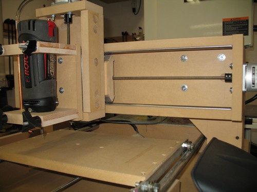
 Here’s the router with the completed Y axis. John’s plans call for
using ½” black iron gas pipe for the rails with 90° elbows, nipples,
and flanges. Although the pipe was fine, I could not get flanges that
were flat enough to give me consistent rail height when I tightened
them down. I switched to ¾” drill rod instead and the results appear to
be quite good. I stacked the two end pieces that support the drill rod
in order to drill the ¾” holes in them and alignment seems to be fine.
Here’s the router with the completed Y axis. John’s plans call for
using ½” black iron gas pipe for the rails with 90° elbows, nipples,
and flanges. Although the pipe was fine, I could not get flanges that
were flat enough to give me consistent rail height when I tightened
them down. I switched to ¾” drill rod instead and the results appear to
be quite good. I stacked the two end pieces that support the drill rod
in order to drill the ¾” holes in them and alignment seems to be fine.
 This is the completed Z axis with stepper motor mounted and ready to
go.
This is the completed Z axis with stepper motor mounted and ready to
go.
 Here’s the completed machine without any of the wiring done.
 Finally here’s the machine with the wiring to the motors completed and
the tool holder completed and mounted.
Finally here’s the machine with the wiring to the motors completed and
the tool holder completed and mounted.
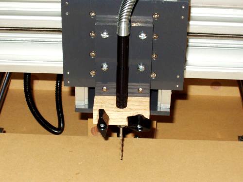 Here’s the tool holder. I’m using a Dremel MultiPro but instead of
mounting the whole unit, I mounted the flexible shaft spindle. This
gives me less weight hanging off the X axis and also mounts the weight
closer in to the axis. So far it seems to work fine.
Here’s the tool holder. I’m using a Dremel MultiPro but instead of
mounting the whole unit, I mounted the flexible shaft spindle. This
gives me less weight hanging off the X axis and also mounts the weight
closer in to the axis. So far it seems to work fine.
 Here’s the finished machine with the computer hooked up and ready to
go. So far I’m using TurboCNC
and it seems to work quite well. The computer is one I had put out of
service. It has a Pentium II 233 and is just running DOS 6.22. I’ll
probably look for an old laptop since it takes up a lot less room but
this works for now.
Here’s the finished machine with the computer hooked up and ready to
go. So far I’m using TurboCNC
and it seems to work quite well. The computer is one I had put out of
service. It has a Pentium II 233 and is just running DOS 6.22. I’ll
probably look for an old laptop since it takes up a lot less room but
this works for now.
I made some simple cuts
on some cedar I had laying around and everything seemed to work fine. I
need to get some carbide bits yet in order to really put it through its
paces. So far with a 24
Volt power supply for the motors and a Xylotex controller
I have been able to get about 18 IPM. That’s in 1/8th microstepping
mode and I haven’t spent any time trying to optimize it yet. I still
have several things to do yet:
- Disassemble and paint all of the MDF pieces
- Verify alignment of all axes
- Cut off ¾” drill rod
- Replace guides on X and Z axes with Delrin pieces
- Mount and wire home switches
- Install an emergency stop switch
- Optimize speeds and accel rates
- Install a table with hold down capability
In the end I made very few changes from John’s plans:
- Used the ¾” drill rod in place of the pipe
- Made slightly different gibbs for the X and Z axes
- Used stainless steel threaded rod – much improved over
standard stuff
Well that’s it – I guess now it’s about time to start thinking about
another machine. I would like to build one with a larger surface –
maybe 24” X 36” and with the capability to take a larger router like a
Porter Cable 690. But that’s another story.
Updated - 02/06/09
It's been a
while since I put together this page and, while I haven't gotten around
to building a bigger router, I have made a number of changes and this
seems like a good time to update this page.
 The
most significant change was replacing the X and Z axes. The
original design utilized aluminum window channel and I could never
really completely eliminate the play in either axis. While
doing
some research, I found the Rockcliff
Machine
site. I liked what I saw, ordered a set of their plans,
and ended up using their skate wheel bearing guided design for both the
X and Z axis. I like the results. Both axes move
quite
easily and exhibit no noticeable play.
The
most significant change was replacing the X and Z axes. The
original design utilized aluminum window channel and I could never
really completely eliminate the play in either axis. While
doing
some research, I found the Rockcliff
Machine
site. I liked what I saw, ordered a set of their plans,
and ended up using their skate wheel bearing guided design for both the
X and Z axis. I like the results. Both axes move
quite
easily and exhibit no noticeable play.
I also used the opportunity to replace the vacuum hose couplers with
some very nice machined couplers from DumpsterCNC.
I also purchase one of their anti-backlash nuts for the Y
axis
and will probably eventually replace the nuts on the other two axes as
well. Their parts are very high quality, reasonably priced,
and work well.
 I
was using a Dremel with a flexible shaft attachment for the tool but
decided I wanted a little more power as well as the capability to use
1/4" shank bits. Since I already had one, my solution was a Roto zip
REV01 tool. It has adjustable speeds, an LED light
to illuminate the
work surface and interchangeable collets for either 1/8" or
1/4"
shank bits. I just built a simple holder that bolts right to
the
front of the Z axis. I actually have several sets of holes in
the
holder so I can move the tool up or down to allow for thicker material.
I
was using a Dremel with a flexible shaft attachment for the tool but
decided I wanted a little more power as well as the capability to use
1/4" shank bits. Since I already had one, my solution was a Roto zip
REV01 tool. It has adjustable speeds, an LED light
to illuminate the
work surface and interchangeable collets for either 1/8" or
1/4"
shank bits. I just built a simple holder that bolts right to
the
front of the Z axis. I actually have several sets of holes in
the
holder so I can move the tool up or down to allow for thicker material.
 I
found I was constantly moving the machine around my shop to make room
for some project or another so I decided to build a rolling stand.
The stand is really simple 2 X 4 construction with some nice
locking casters. I also added a drawer to store bits and
other
pieces and finally a pullout shelf for the laptop I use to run the
router.
I
found I was constantly moving the machine around my shop to make room
for some project or another so I decided to build a rolling stand.
The stand is really simple 2 X 4 construction with some nice
locking casters. I also added a drawer to store bits and
other
pieces and finally a pullout shelf for the laptop I use to run the
router.
 Here's
another picture of the stand with the shelf and laptop all tucked away.
Here's
another picture of the stand with the shelf and laptop all tucked away.
 I
also made a few electrical changes. I added an E-Stop
switch, new
motors, and, since I am approaching max current on the Xylotex drives,
a fan for cooling. For the most part this has all worked
well.
However I still have an issue with the new motors.
I went
from 80 oz.in. motors to 282
oz.in. motors from Keling
Inc.
and, while the new motors
have a great deal of torque, I haven't yet figured out how to get as
much speed as I expected out of them. I'm still working on
this
problem and expect I may need coarser drive screws. I'm also
planning to add a relay board that I purchased from Probotix
to automatically control the Rotozip switch as well as the drive
enables.
I
also made a few electrical changes. I added an E-Stop
switch, new
motors, and, since I am approaching max current on the Xylotex drives,
a fan for cooling. For the most part this has all worked
well.
However I still have an issue with the new motors.
I went
from 80 oz.in. motors to 282
oz.in. motors from Keling
Inc.
and, while the new motors
have a great deal of torque, I haven't yet figured out how to get as
much speed as I expected out of them. I'm still working on
this
problem and expect I may need coarser drive screws. I'm also
planning to add a relay board that I purchased from Probotix
to automatically control the Rotozip switch as well as the drive
enables.
 Here's
a picture of my latest project. I decided to make some
ornaments
for Christmas presents for friends and family and got a little carried
away. I ended up making 8 sets of 8 ornaments. Each
ornament in a set is a different species of wood. I used
cherry,
walnut, mahogany, alder, maple, birch, oak, and poplar. The
ornaments are approximately .080" (2 mm) thick and I used a 1/16"
diameter solid carbide bit for the machining. Some of the
woods
(cherry and mahogany) machined very nicely and others ( birch and
maple) were a little more problematic. All in all I learned
quite
a bit about machining different woods. Below are some
pictures of
individual ornaments and details of the software process.
Here's
a picture of my latest project. I decided to make some
ornaments
for Christmas presents for friends and family and got a little carried
away. I ended up making 8 sets of 8 ornaments. Each
ornament in a set is a different species of wood. I used
cherry,
walnut, mahogany, alder, maple, birch, oak, and poplar. The
ornaments are approximately .080" (2 mm) thick and I used a 1/16"
diameter solid carbide bit for the machining. Some of the
woods
(cherry and mahogany) machined very nicely and others ( birch and
maple) were a little more problematic. All in all I learned
quite
a bit about machining different woods. Below are some
pictures of
individual ornaments and details of the software process.
 I used
several software packages in the process. Most of the
ornaments were published in a November, 2007
issue of Wood Magazine as
scroll saw plans. I scanned them into bitmap files and then
imported them into the freeware version of WinTopo
which I used to
convert the bmp images to vector images, scale them to the appropriate
size, and save them as dxf files. I used DeltaCad
to verify the files and the finished image sizes.
DeltaCad also now has the capability to move individual
points to
make it easier to clean up drawings. Another option that I
will
try next time is to import bmp files into DeltaCad and then draw over
these files on a new layer and export that image as a dxf file.
I
then imported the dxf files into Sheetcam
TNG where I specified the
tool sizes, material size and toolpath offsets. Sheetcam then
produced the G-Code
files to run on my router. I also used CNC
Simulator to test the files and verify that they would cut
correctly.
Finally the files were loaded into Turbo CNC
to do the actual
cutting on the router. It was quite a process and it took me
numerous trials to get everything correct. In the end I was
quite
happy with the results.
I used
several software packages in the process. Most of the
ornaments were published in a November, 2007
issue of Wood Magazine as
scroll saw plans. I scanned them into bitmap files and then
imported them into the freeware version of WinTopo
which I used to
convert the bmp images to vector images, scale them to the appropriate
size, and save them as dxf files. I used DeltaCad
to verify the files and the finished image sizes.
DeltaCad also now has the capability to move individual
points to
make it easier to clean up drawings. Another option that I
will
try next time is to import bmp files into DeltaCad and then draw over
these files on a new layer and export that image as a dxf file.
I
then imported the dxf files into Sheetcam
TNG where I specified the
tool sizes, material size and toolpath offsets. Sheetcam then
produced the G-Code
files to run on my router. I also used CNC
Simulator to test the files and verify that they would cut
correctly.
Finally the files were loaded into Turbo CNC
to do the actual
cutting on the router. It was quite a process and it took me
numerous trials to get everything correct. In the end I was
quite
happy with the results.
 Here's another sample ornament.
 And
one more.
And
one more.

Here are some more new ornaments.
This
has certainly been an interesting learning experience. I'm
still
getting my head around some of the things you can do even with a small
machine. My last project was cutting the openings in the face
and
back of my Internet
Clock. This was much easier than previous
attempts. The final packaging has always been my least
favorite
part of electronic projects but this machine is quickly changing that.
My next step is to figure out these new motors and what I have to do to
get more speed. More to follow.....
Updated 12/05/09
Well,
after doing quite a bit of research, it seems I need dampers on the
axes to eliminate or reduce resonance and get more speed.
There
are several sources for commercial dampers but they all seemed to be
quite expensive. There are also several hobbyist web sites
with
examples of homemade dampers. One excellent source of
information
is the Solsylva
web site. There's also lots of information on this thread
on CNCZone. And here's some commercial
dampers.
The concept didn't seem too difficult so I set out to make my own and
this is what I ended up with:
The
first picture is the X axis and the second picture is the Y axis.
You'll notice that the Y axis damper isn't installed on the
motor
shaft, it's actually installed on the opposite end of the lead screw.
I had to do this because I didn't have enough room at the end
of
the Y axis motor shaft and, as it turned out, this was just as
effective as the damper mounted directly on the motor shaft.
The
parts were very simple. Each damper was composed of 2
#9961K15
clamp collars purchased from McMaster Carr
@ $2.67/ea. One 3/8" ID part #3388 T-Track roller purchased
from Peach
Tree Woodworking @ $6.99 for two. One compression spring from
ACE
Hardware @ $0.69/ea. One 2-1/4" piece of aluminum tubing
0.375" X 0.065" X 0.245" purchased from Online
Metals
@ $3.59/12". The total cost for each damper was about $10.19.
In reality I spent more for shipping than the cost of the
parts
although the spring was local and I purchased the rollers at a
woodworking show.
The only thing I had to do was open up the ID
of one of the pieces of tubing slightly since the ID was 0.245" and the
motor shaft was 0.250". I did this with a 1/4" drill bit on
my
drill press. My lead screw was already 0.244" OD so I didn't
need
to do anything for that one.
So, how did it work? Until
now, the fastest I had been able to run these two axes reliably was
between 15 and 20 ipm. I am currently able to run them both
at 75 ipm and, in fact, I really haven't tried to go any faster.
That's plenty of speed for my little router.
Needless to
say I am extremely pleased. In case you're wondering, I
didn't add a damper to the Z
axis
since I really didn't see much need for it.
Well that's where I
am for now. Not sure what my next improvement will be - but
it
will probably be improved dust pickup and control.
Updated 7/19/10
Well I still haven't done anything about dust control but I have
attempted to do an inlay and it came out really well. This is
a
small oak box with walnut accents and the inlay is also oak and
walnut. My first attempt was with material about .040" thick
but
that proved to be a little too fragile. This inlay was about
.080" and it was just right. The cutter I used was a .0625"
diameter solid carbide spiral bit and worked well.
Updated 11/26/10
It seems like things
are always changing. After the last box I decided that, if I
wanted to make finer inlays, I would need a more accurate spindle.
The RotoZip worked fine for the ornaments but, when I worked
on
inlays, I was constantly modifying the tool size slightly to get the
correct final part dimensions. With accuracy and reasonable
cost
in mind, I decided on a spindle from CNC on a Budget.
This little spindle takes bits with 1/8" shafts and can run
on
either AC or DC (I am currently running on AC but may change in the
future). The spindle has a three step pulley and Paul states
in
the FAQ
that they
run at 7500, 15000, and 30000 RPM. In practice I found that
they
run a little slower but certainly fast enough for what I do.
Here's a picture of the spindle installed on my router.
I also changed my software. I had been using TurboCNC
on a laptop but, since it runs in DOS, I had trouble getting it on my
network and I finally got tired of running a floppy disk back and forth
from the PC I was using for drawing and creating G-Code to the laptop.
My new software is EMC2
which as an open source machine control program which runs under Linux
- specifically Ubuntu. I installed EMC2 and Ubuntu on a 2.6
Ghz
Asus PC that I picked up for $50 and which I also set up to dual boot
Windows XP. The learning curve for both Ubuntu and EMC2 was a
little steep but not too bad. I'm quite happy with the result
and
am glad I made the switch. Here's the new setup.
So
I decided to make another box with an inlay to test out the new setup.
This box is cherry and maple and only about 3-1/2" X 5" X
2-1/2"
high. The actual circle that contains the inlay is 2" in
diameter. I also decided that, in order to make finer inlays,
I
needed a smaller bit. The inlay was cut from .050" stock with
a
1/32" diameter bit. I was a little worried about using a bit
that
small but it worked great. The bit came from Stewart-MacDonald
and ran about $18.00. I have also recently purchased some
3-flute, solid carbide, 1/16" diameter cutters from Atlas
Billiard Supplies and have been very impressed with their
performance. So here's the latest box.
Finally I recently cut a set of ornaments for a cancer survivorship
workshop that I help to facilitate. I used Inkscape
to design the ornament and can see that I will be using this software a
lot more in the future. Inkscape is a scalable vector
graphics
drawing program and, although open source, is incredibly powerful and
has a vast array of features. Besides creating easily
scalable
images from scratch, it's easy to import bitmaps and then create an
outline in vector graphic form to import into Sheetcam for final G-Code
creation. Here are the new ornaments in oak.
And here's a set for another class but in cherry this time.
And another set in walnut.
I
recently completed a blanket chest for my daughter and she convinced me
that I needed some way to sign some of my projects. After some
thought I decided on a small engraved wooden medallion that I could
glue to a project. I actually learned quite a bit making this.
I decided to make sort of a sandwhich of maple over walnut and
then engrave through the maple to expose the walnut. I started by
glueing a thin piece of .020" thck maple to a piece of .100" walnut.
When I unclamped the pieces, they were bowed badly. I had
heard about veneering both sides of a board to prevent bowing but
hadn't really thought of this as veneering. When I made a new
piece that I veneered on both side, it worked fine. I started by
using a 30 degree engraving bit to engrave the text and saw image but
it just didn't look good. For the final result, the text and
image are engraved with a 1/32" diameter cutter and the medallion came
out great.
Updated 11/18/14
I
realized I haven't made any updates to this page in a long time and I
have added several changes to my CNC Router. The two significant
changes are to add a new spindle and finally add dust collection.
The new spindle, like the prvious one, came from Paul Jones and CNC on a Budget. The new spindle has a bigger motor and uses ER-11 collets
instead of fixed 1/8" shank tools. Collets are available from
1/16" up to 1/4" and work very well. The previous spindle,
although it also worked very well, caused some problems with the allen
wrench slipping in the very tiny set screw and sometimes the tool
sticking in the spindle. No problems like that with the new
spindle. Here's a picture.
You
can also see the new dust skirt in this picture. It's made out of
a couple of pieces of plastic with magnets embedded in the corners and
some strips of flexible clear plastic. It ended up being so
simple that I don't know why it took me so long to implement. I'm
using a Sears 2.5 gallon, 2 HP vacuum that I picked up for $25. and the
combination works great - virtually no dust problems. Here's a
picture of the dust skirt and the new collet.
And here's the vacuum.
That's all for now.
Thanks for visiting.
Contact
Home


