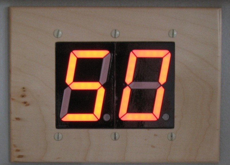
My wife and I get up early and walk most mornings and we wanted a way to know the outside temperature before we ventured out of the bed. We looked at some of the wireless models but the bed was too far from the display to see the temperature. Since my Homevision home control system, already has the outside temperature based on a direct connect analog temperature sensor, I decided I would see if I could build a display that was large enough to see from across the room. Here's a picture of the finished display, read on to see the hardware and software details.
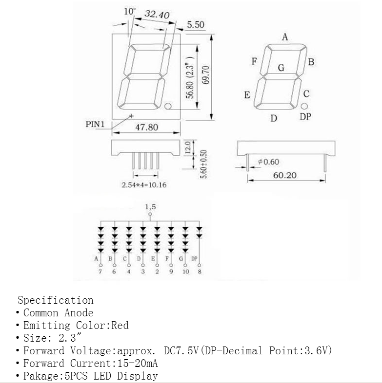
Of course the most important piece of hardware was large LEDs that would be easily visible from across the room. I ended up finding exactly what I wanted on Ebay. I purchased 5 - 2.3" LED displays for about $9.00. Here's the only data I was able to find, but it had all of the data I needed.
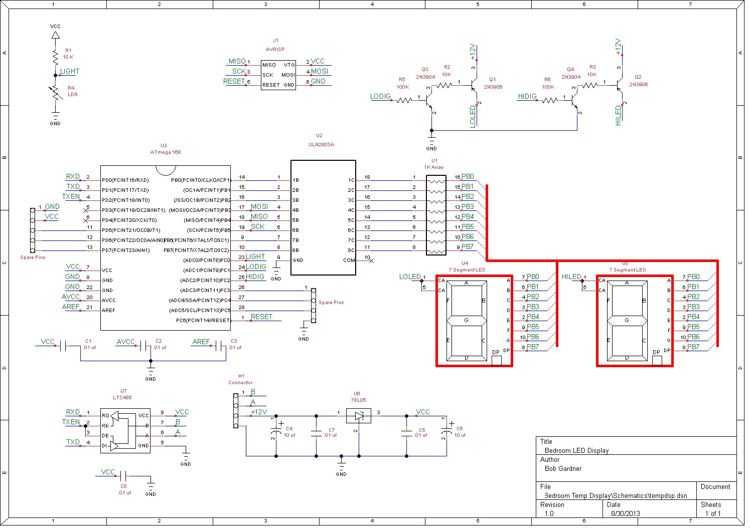
Once I had the displays it was time to specify the rest of the hardware. I chose to use an ATmega controller from Atmel to control the display. It was too far from the controller to send the temperature via a serial link so I decided to use RS485 as a communication protocol. I needed to drive the displays from a voltage greater than 7.5V as you can see from the display data and I had 13.3V available from the main controller, so I chose to use that voltage. Due to the fact that the ATmega168 and the LTC485 were limited to 5V, I needed to use a high side driver to control the 13.2V for the display. Finally I added an LDR (light dependent resistor) to detect ambient light levels so that I could dim the display at night. Once I had the schematic nailed down, I designed a custom PCB to make the job easier and more professional. Here are the schematic and PCB, you can click on the thumbnails to see a full size image.
 |
 |
And here's the front and back side of the finished PCB.


